


Furnace waterwall slagging is a common low NOx combustion problem. Slagging is commonly a result of staged combustion and excessive coal imbalances, leading to high carbon fly ash that can deposit on furnace waterwalls. Both bulk and locally reducing atmospheres can yield low-melting ash phases, increasing furnace slagging potential. There are several means to minimize reducing conditions and furnace slagging: pulverized coal nozzle balancing devices, CFD simulations to design flow corrections devices for balancing burner secondary air flow, and sufficient air to blanket furnace side walls.
Furnace waterwall corrosion can also occur due extreme reducing conditions near tube surfaces. Tube failures often result from localized reducing conditions and flame impingement on the furnace rear wall. Analysis of these tube failures has shown tube cracking due to thermal fatigue and breakdown of the protective oxide layer. In order to eliminate rear wall corrosion we have designed a special air flow system to blanket the rear wall, especially for boilers with limited space.
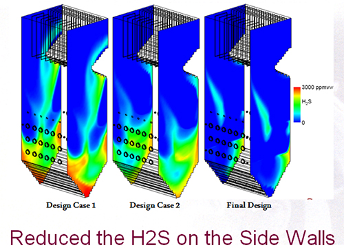
Sidewall corrosion can also occur with low NOx combustion due to reducing conditions in the burner zone as a result of staging with OFA. This type of failure is generally due to sulfidation of the tube oxide layer from iron sulfides in the ash in a reducing atmosphere. CFD modeling is used to design air ports and identify their location between the outer burners and the sidewalls. Special design features such as tilt and yaw can be incorporated into these ports to ensure air coverage of potential corrosion regions.
Furnace waterwall slagging and corrosion are unique to the fuel fired, furnace operating conditions and design of each individual boiler. As a result, we evaluate the existing conditions responsible for corrosion and apply a cost effective, engineering solution. A brief summary of slagging and corrosion phenomena and solutions is shown below.
|
Phenomenon
|
Cause Analysis
|
The results
|
Our solutions
|
|
Excessive staged combustion
|
Delayed combustion flame, pulverized coal-rich region due to the high carbon content in fly ash, low melting iron sulfides in a reduced state, deposition on the wall.
|
Increased slagging
|
◆Unique burner nozzle design to achieve a fuel and air staging, strengthen early combustion to reduce NOx, less OFA required;
◆.Optimize burner design parameters to balance combustion area heat load.
|
|
Uneven distribution of secondary air
|
The ash carbon content increases, thereby increasing slagging;
Poor burner throat flame performance; |
Increased slagging
|
◆.Unique secondary register design allows adjustment for better mixing.
◆.Secondary air system CFD simulation, design and installation of flow correction devices to optimize uniformity.
|
|
Combustion control and regulation problems performance; poor flame shape.
|
Poor combustion results in a delayed flame and reducing atmosphere with low melting iron ash species.
|
Increased burner zone slagging and corrosion occurs.
|
◆Unique two zone register design, effective control of flame shape, close ignition point advance, enhanced combustion.
|
|
Excessive reducing conditions near sidewalls
|
Poor combustion of outer burners due to insufficient air, high carbon content and low melting fly ash impacts sidewalls
Secondary air or OFA design is unreasonable, excessive localized reducing atmosphere;
|
Sidewall slagging, and corrosion
|
◆Primary air and secondary air balancing equipment for more complete combustion, reducing unburned coal particles near the wall.
◆Increase sidewall air with specially design ports to create oxidizing atmosphere
◆Special wall air supply system design using membrane slots.
|